STRANGER Robot alu metallic

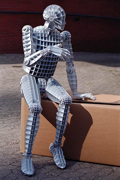
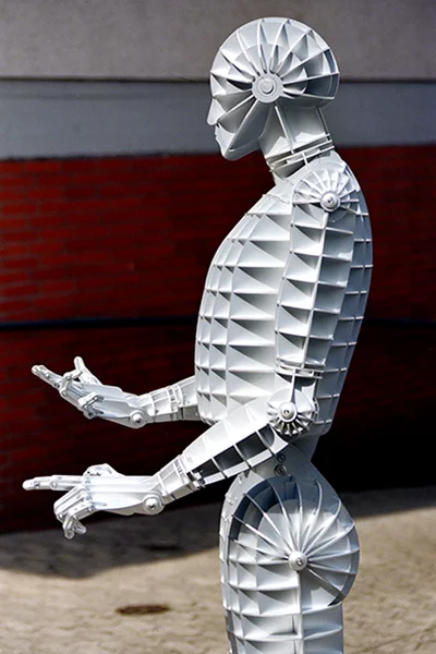
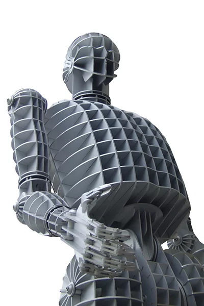
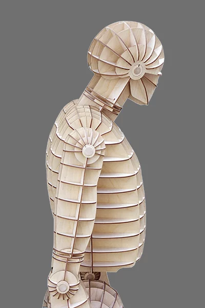

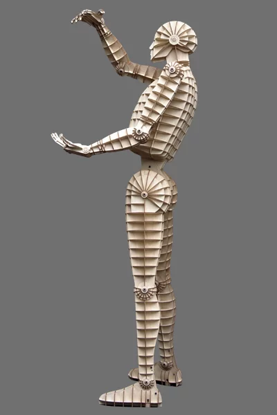
Ergonomics and Range of Motion
Design Options
Passive Joints & Artificial Muscles
Bionic Robot with passive
joints
The licensee integrates its proprietary
artificial muscle technology and adapts the STRANGER robot
chassis design accordingly.
-
Design Option
Bionic Robot with full-body Elasticity
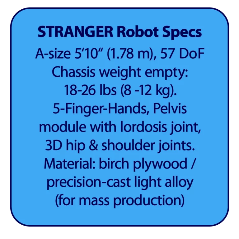
Chassis A-Size 5'10" / 1.78 m with 57 DoF
Chassis weight empty 18-26 lbs / 8-12 kg
Total robot weight: 120 lbs / 55 kg (target)
Equipment weight: 100 lbs/ 45 kg (target)
Passive joints (alu, steel), rubber muscles with tendons, e-motors, servos, sensors, wires, screws, Jetson module, vision system, and battery
-
Physical
Principle
Pulsed passive walker
-
Proposal Muscle
Design
Natural rubber (NR) with high energy storage density. Tensile strength 3–12 N/mm², up to 24 N/mm². For comparison: tensile forces in the physiological (i.e., effective) muscle cross-section in humans are reported to be 0.3–1.2 N/mm². The literature varies—as do the various skeletal muscles—between these values. A rubber cord with a cross-sectional area of 1 mm² is therefore 10 times stronger.
-
Muscles made of natural
rubber (NR) can withstand 100 to 200 million load cycles.
NR is a highly elastic material with outstanding physical
properties (up to 300% elongation), excellent mechanical
strength, fast response times (ms), and very good
performance even at low temperatures (-45 to
90°C).
-
Natural rubber is
inexpensive, lightweight, durable, hygienic and
biodegradable.
- Rubber muscles can be designed in various ways: with directly tensioned muscle fibers, or with twisted rubber strings. The second option is particularly suitable when one wants to achieve isometric muscle work, i.e., when one wants to regulate the tensile stress—and thus the force—while keeping the length constant.
-
Muscle Tension
Regulation
active (electromotors) & passive (gravity, accelerations)
-
Implanted Automatic
Force Sensitivity
Tensioned rubber cords are excellent reversible energy storage devices. They function not only as spring and damping elements, but also as force sensors. Any change in the applied forces, whether internal or external, is sensed by the material and triggers reflexive responses. This essentially eliminates the need for expensive force sensors. The stretch of the rubber cord, which corresponds to a specific force, could then be measured using low-cost sensors. The entire robot body essentially functions like a multi-channel force sensor—even without any electronics.
-
Energy
Consumption
Walking mode approx. 240 W (target):
1/3 = 80 W actively supplied by e-motors
2/3 = 160 W passively supplied by potential energy (gravity, muscle pre-tension)
-
Chassis
Material
Birch plywood natural, lightweight, strong, high modulus of elasticity, antistatic, and biodegradable
-
Fast, Cost-Effective
Manufacturing
Rapid laser manufacturing of the robot's chassis parts in just 4–6 hours. That's 100 times faster & cheaper than 3D printing
-
Design
Options
Color or metallic finish, protection clothes, waterproof plywood, light alloy casting for mass production, body cover parts
Active Joints vs Passive Joints
Robot with active
joints:
The licensee integrates its proprietary
actuator technology and adapts the STRANGER robot chassis
design accordingly. This design strategy is particularly
well-suited for lightweight, “athletic” robots equipped with
direct-drive torque motors at the shoulder, hip and knee
joints, and would be a great fit for the STRANGER lightweight
chassis.
Pros & Cons Active
Joints
- Advantages: Active (motor-driven) joints are now technically mature and applicable. As developments since 2023 show, motor joints with harmonic drive or planetary gears, rotary and linear actuators, sensors, software and AI are capable of mastering the complex dynamics of a multi-joint kinetic system.
-
Among the most fascinating aspects are the high power-to-weight ratio, the fully integrated modular design, and the ability to incorporate spring-like properties—that is, the elasticity and compliance of the robot joints—into the motor-gear combinations using only software and sensors. In this way, the stiffness of the joints can be continuously adjusted within milliseconds from soft and compliant to hard and rigid.
- Disadvantages: Active motor-driven joints are the main cost factor and worsen the power-to-weight ratio, primarily due to unfavorable lever ratios. They require custom made motors with high torque density, reduction gears with high gear ratios combined with low reflected inertia (a nearly impossible trade-off), zero backlash, and sophisticated torque and position sensor systems. And they force us to develop complex software control systems. The computational demands are enormous—without onboard supercomputers and AI, it would be impossible to control the complex dynamics of a bipedal robot composed of active, motor-driven joints.
Pros & Cons Passive Joints
- Advantages: Biological systems have passive joints that are moved by muscle-tendon actuators. They are not controlled by software, but apparently function according to much simpler principles: an elastically pretensioned skeleton enables passive dynamics and elastic behavior that embodies a morphological intelligence. This results in natural, reflexive behavior coordinated by muscles whose activities are amplified or inhibited by neural networks. The entire system is based solely on forces. Such design principles would largely eliminate the need for expensive force sensors—as well as most of the computational effort required by robots with motor-driven joints.
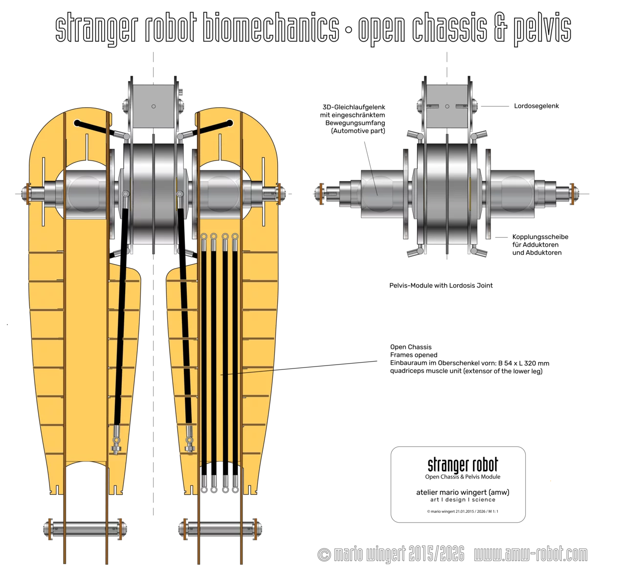
- Passive joints are simple and non-expensive. They can be combined with muscle-tendon actuators made of rubber cords, whose tension is regulated by standard electric motors. The motors can be positioned at the most optimal locations. If useful, muscle-tendon actuators could also be supplemented by direct-drive torque motors (this design option can be implemented in the pelvic module of the STRANGER robot, which has space for two torque motors).
-
Disadvantages
Real artificial muscles, such as dielectric elastomer actuators (DEAs) are still in the early stages of development. Muscle-tendon systems made of natural rubber or PA-strings (fishing line) are used in some experimental projects and robotic arms, but not yet in fully functional life-size robots, as far as is known.
Furthermore, their elastic behavior is subject to complex nonlinear dynamics that are essentially impossible to simulate and control algorithmically.
Problems: Cost, Durability, Safety
Physical
Limits
Despite all the extraordinary
progress that has been made made in recent years (there are now
at least 50 major companies worldwide that aim to manufacture
humanoid robots), motor joints are not actually the optimal
solution for bipedal robots. So far, this has been the main
approach, though it is sometimes combined with muscle-tendon
actuators, particularly for the hands. However, the design of
motor-driven joint systems is already reaching its physical
limits.
As a result, two main categories have emerged among humanoid
robots: lightweight, fast, and more affordable robots, and
heavier, slower models that, while capable of handling heavier
loads, are physically unable to walk in a natural and graceful
manner due to their sheer strength. The higher gear ratios in
their transmissions make them practically “blind” to reaction
forces below a certain threshold (keyword: reflected inertia),
which is why they are only allowed to take small steps. Even a
pebble could cause them to stumble.
Cost per Motor-Driven
Joint
Approx. 1,000–6,000 US-Dollars in mass
production. The massive demand for motor-driven joints and
special linear actuators for robots—of which several million
units are expected to be produced in the coming decade—is
likely to lead to material and supply shortages as well as
rising prices.
Service Life of
Motor-Gear Combinations
Another problem is the durability
and cycle life of the motor-gear combinations. Just imagine the
reaction forces acting on the robot with every step. Depending
on the state of motion, these forces can reach several times
the robot’s body weight. These forces must be able to act
passively and reverse the joint motors; otherwise, they will
immediately destroy the gears. Or the robot loses feedback with
its environment because it doesn’t sense the reaction forces
acting on it at all. This is also a security issue.
Load Cycle
Estimation
A person walking takes about
7,200 steps per hour. That’s 57,600 in 8 hours, 1.728 million
in a month, and around 21 million in a year. For a robot with a
five-year lifespan, that amounts to more than 100 million
impacts and motion cycles that the motor-gear combination would
have to withstand. This is a reasonable estimate for the
required cycle endurance, even if the robot does not walk that
much and performs other movements.
Force Sensitivity: Actio
= Reactio
To walk effectively and perform physical work, a bionic robot
requires morphological intelligence: a body that senses all
forces (acceleration and gravity) and reacts reflexively to
changes in real time. All of this is based on the fundamental
principle of mechanics: Actio = Reactio. This principle can and
must be integrated into the robot’s mechanical structure from
the very beginning—with the highest possible force sensitivity
in both directions, based exclusively on elastic
pretension.
Toward an Optimal Biomechanical
Design
The goal is to understand the
holistic nature of such an elastic biomechanical system and to
optimize its physical behavior through structural measures in
such a way that both energy consumption and control effort are
minimized.
Cleverly designed muscle-tendon
actuators would be lighter, more robust (100 to 200 million
load cycles), more energy-efficient, and fully elastic. From a
purely physical standpoint, they would be superior to
motor-driven joints and at least ten times more
cost-effective.
However, such physically-elastic
systems are very difficult to train on current AI physics
engines—unless there are attractors, i.e.,
deviation-resistant, self-stabilizing dynamic system states of
the robot that the AI can identify and navigate toward
directly.
To figure this out and make progress with this technology, many
more real-world experiments are needed.
Conclusion
Even though many of the newly
emerging humanoid robot start-ups have high hopes, the
functionality, cost-effectiveness, safety, and autonomy of
humanoid robots have yet to be tested—a process that, as with
the full autonomy of self-driving electric cars, could take 5
to 10 years. So we still have some time; nothing is certain
yet.
We may well find that it is far more cost-effective to pay a
worker—who can easily withstand several billion load cycles
over the course of his working life—60,000 dollars a year than
to employ a robot, which is cumbersome compared to a human,
costs 60,000 dollars or more per year in maintenance and
depreciation, and is capable of doing much less. And who
certainly won’t be buying the products they manufacture. This
is where macroeconomics comes into play. So we still need to
figure out which applications are truly useful and
cost-effective.
With the STRANGER ROBOT project, we are essentially working on
technologies that foreshadow artificial muscles. That is why we
should strive to a better understand the biomechanics of
elastically pretensioned robots and, above all, to implement
them experimentally, since physical simulations alone are not
sufficient for this purpose–and, due to the nonlinear behavior
of rubber muscles, are also hardly practical.
This includes the effects of muscle loops spanning multiple
joints, the optimal configuration and placement of the
muscle-tendon actuators, and an anatomical or structural design
of the knee and hip joints that ensures the robot consumes
virtually no energy while standing, without losing its passive
responsiveness.
Artificial muscles and applications for humanoid robots are
still in the development stage, in part because, until now,
there has been no cost-effective skeletal structure (i.e.,
standard platform) available for experiments that could be
equipped relatively quickly with artificial muscles and thus
with morphological intelligence–a need that can now be met by
the STRANGER ROBOT R&D CHASSIS.
Coming Next: Proof of Concept
An initial rough assessment of whether the required specifications can be met under the most extreme load condition–standing up from a squatting position against the body weight of STRANGER. Assuming 480 N = 48 kg (106 lbs) weight, without the weight of foot & lower leg, and using a rubber-muscle-tendon system driven by ordinary e-motors:
1) What pretensions are generated in the rubber cords passively by lowering into a squat?
2) How work the muscle groups in the lower leg and thigh together? Are the hip and back muscles involved?
3) What contribution makes the rotation of the pelvis around the hip joints, caused by activated spline muscles and hip drives, the torso's inclination, and the position of the arms to shorten the the load-lever arms?
4) How much tension force must be generated in the thigh and calf muscles, the hip joint drives, and the spline muscles, in addition to the pre-tension, for a brief moment to initiate the rise from the squat?
5) What is the required torque of the electric motor(s), and what is its mass?
6) What is the optimal
muscle-tendon-motor design configuration?
In bio-inspired humanoid robot design, there is still plenty to
explore, invent, and improve.
Answers
See also the animation videos "Biomechanik Bein passiv B" and "STRANGER ROBOT biomechanics–standing up from a squat" (below)
RE 1) If the weight of the humanoid robot STRANGER is 48 kg or approximately 480 N (excluding the feet and lower legs) and the load lever arm is 0.2 to 0.27 m long, this results in a torque of 48 to 65 Nm per knee. It follows that: With a force lever arm of 60 mm at the knee, a tensile force of 1,200 N must be applied to the lower leg extensor to achieve equilibrium. This theoretically generates a torque of 72 Nm in the knee (i.e., slightly more than 65 Nm).
RE 2) The lower leg extensor muscles are located on the front of the thigh. Their tendons are routed around the knee and pull on the shinbone. They work together with the calf muscles to form a functional muscle loop. Together, they hold the knee joint in position.
Since the sole of the foot is in contact with the ground, the calf muscles act as extensors of the lower leg at this moment: they pull the lower leg backward with the knee—against the applied load. This is the reverse of plantar flexion (during which the calf muscles normally extend the foot). Reverse plantar flexion thus helps reduce the tensile stress in the thigh muscle through its counteracting force.
RE 3) When lowering into a squat, the work is essentially performed passively by the robot’s own weight—that is, by gravity. The lower leg extensors are stretched further and further, causing the tensile stress on the muscles to increase steadily. On the one hand, they slow the downward movement; on the other, they store potential energy. With skillful control, the pre-tension of the muscles can be increased while they are relaxed or before lowering, so that the motors that tension the muscle-tendon system rarely have to work against the full passive tension. Clear is that the movement of other body parts, such as the pelvis, arms, and chest, can influence the length of the load lever and thus the position of the center of gravity. The extent to which this is relevant during a squat has yet to be determined.
RE 4) When squatting, the lower leg extensors must generate enough tension to support the body’s main weight while maintaining pseudostatic balance. In this squat case study, each lower leg extensor of the STRANGER ROBOT, located at the front of the thigh, consists of eight STRANGER RUBBER MUSCLES that exhibit an exceptional force-strain curve. Each was stretched by 115%, thereby exerting a tensile force of approximately 150 N. Together, they generate 1,200 N, which produces a torque of 65 Nm - up to 72 Nm - at the knee (130 Nm up to 144 Nm at both knees). So, theoretically, this amounts to 1200 N per leg in the static equilibrium of the squat. However, the extensor muscle loop also includes the calf muscles (and others), which reduce the theoretically required tension in the thigh–possibly by as much as one-third. Whether this assumption is correct still needs to be verified through physics simulations and experiments.
Since there may still be a
payload, we'll stick with the assumption of 1,200 N for now.
Once these 1,200 N have been passively generated, only a small
additional amount of force needs to be applied to initiate the
rise from a squatting position. Incidentally, this could also
be achieved by moving limbs such as the arms or the pelvis in a
way that shortens the load-bearing lever arms. When fully
tensed in static equilibrium, only the inertia of the upper
body needs to be overcome to stand up. Since the system is
“suspended” under tension in equilibrium, impulses of only a
few Newton are sufficient for this. These impulses consist of
additional tensile forces, which are ideally applied by a
separate “control or initiation muscle” that had previously
been under little or no tension. Only minimal motor forces are
required for this. This principle is explained and illustrated
in even greater detail to licensees. As the humanoid robot
stands up, the load levers continue to shorten, resulting in
less and less tensile stress in the rubber cords, which
consequently shorten until they reach their basic
tension.
RE 5) Let’s
assume we need a standard electric motor that is supposed to
apply a tensile force of 150 N to a rubber cord. To do this,
the motor winds the tendon—a 2-mm Dyneema cord or a fishing
line—directly onto its shaft, which has a diameter of 3 mm.
This determines the lever arm and the required torque: r = 1.5
mm + 1 mm (half the diameter of the Dyneema cord) = r = 2.5 mm
= 0.0025 m × 150 N = 0.375 Nm. The motor would therefore need
to have a torque of 375 Ncm. If the diameter of the motor shaft
can be made smaller, the torque can also be reduced
further.
To protect the motor shaft from
bending stresses, we position the tendon string so that it
pulls on the shaft from both sides and both sides are wound in
opposite directions simultaneously. Winding the cord on both
sides tensions the rubber muscle more quickly and also
neutralizes the tensile forces acting on the motor shaft when
the rubber cord is fully tensioned. In this state, the motor is
not powered but can detect passively induced torques and thus
function as a sensor (more details and corresponding drawings
are provided to licensees).
Since the motor runs for only a
very short time—the maximum possible string length is wound up
on both sides after about 6-25 revolutions—the motor can
presumably be designed for the stall torque, which is
significantly greater than the effective torque. This means
that the motor can be even smaller, operates in start-stop
mode, and could therefore also be a standard, inexpensive DC
brush motor. The weight of such a motor can only be specified
once the exact specifications are available, but it will likely
be between 250 g (target) - 450 g (maximum).
Torque Density at the
knee joint
If the lower leg extensor muscles on
the front of the thigh, including the motors, weigh a total of
4 kg, the torque density at the knee joint would be 18 Nm/kg
(72 Nm/4 kg). If we could reduce the weight of this muscle
group by half through optimal design and fine-tuning, the
torque density would double to 36 Nm/kg (72/2)—which would
currently be among the highest values achievable. Once the
design of the artificial muscles and their various applications
have been clarified, we will seek expert advice from selected
manufacturers regarding the design of the respective electric
motors. We also need to determine whether it makes sense to
group four muscle-tendon units in the thigh into a single unit
that can be driven by just one motor, so that we only need two
motors per leg for the quadriceps muscle group—that is, the
lower leg extensors.
RE 6) Some
considerations have already been mentioned. The detailed rubber
muscle design will be made available exclusively to licensees.
Licensees are, of course, free to develop their own, improved
solutions. But even in this case, the proposed design of the
STRANGER ROBOT’s artificial muscles can serve as a template,
since the geometry and mass ratios remain essentially the
same.
Stress-Strain Behavior of the STRANGER ROBOT’s Artificial Muscles
The artificial muscles of the STRANGER ROBOT are made of natural rubber, which has a stress-strain curve that is particularly well-suited for this purpose:
1. In the main operating range of 40 to 90 N (considering a single rubbber muscle cord), the STRANGER ROBOT muscles behave in a virtually linear manner, while they exhibit steep increases in the range of muscle pre-tension (basic muscle tone) and maximum elongation.
2. In the range of baseline tension, they exhibit a steep, likewise nearly linear increase from 0.2 N to 20 N at an elongation of 0.2 to 2.5 mm. The knee joint driven by the muscle is thus relatively stiff at the onset of force application, without losing its sensitivity to reaction forces.
3. In the range of 2.5 to 7 mm of elongation, the tensile stress increases to 30 N, then transitions into the linear behavior range at 25 mm of elongation and a stress of 45 N. The knee joint becomes more compliant and responds in a nearly ideally elastic manner over a wide range of forces.
4. If the strain exceeds 90%, the stress doubles nonlinearly from 90 N to 180 N over the next 50 mm of strain—and rises even more steeply once the strain exceeds 110%. The stiffness of the knee joint thus increases significantly without losing its responsiveness.
Conclusions
Re 1)
The wide linear operating range is likely to prove
advantageous for dynamic simulation in the physics
engine.
Re 2)
The behavior in the range of basic tensions suggests excellent
force sensitivity. Reaction forces are detected as low as 0.2
N. At the same time, disturbances are strongly damped, which
implies passive self-stabilization.
Re 3)
It remains to be clarified whether the active control
range—which in this artificial muscle design is achieved via
electric motors—can be limited to the linear range, while
higher stresses are generated purely passively through
pre-stretching as the robot assumes appropriate postures.
Consider, for example, athletes who use this method to ensure
maximum force development in the respective muscle
groups.
Force-strain diagrams, detailed specifications, and sources of supply will, of course, be made available to licensees.
The grace of walking is an expression of the underlying physics
...claims the artist and creator of STRANGER
Seven Reasons to get a STRANGER ROBOT Design License
The humanoid robot STRANGER is characterized by a unique plate-skeleton-design with fractal complexity that is nonetheless based on simple geometric rules. This design is particularly well-suited for rapid laser-cutting prototyping during development and testing phases, as well as for manufacturer kits, and perhaps even affordable DIY kits.
The design strategy is also unique: While the size, ergonomics, kinematics, and range of motion of a humanoid robot are, in principle, invariant design targets (these parameters are ultimately intended to correspond to those of the average adult), the drive and control principles are subject to rapid scientific and technological progress. For this reason, the design strategy was divided into two main components: The chassis, with at least 57 degrees of freedom (DoF), represents the ergonomic and kinematic invariants and serves as a universal biomechanical platform in the R&D and prototyping process. The nature of the drive and control concepts represents the variables that can be integrated according to the state of the art.
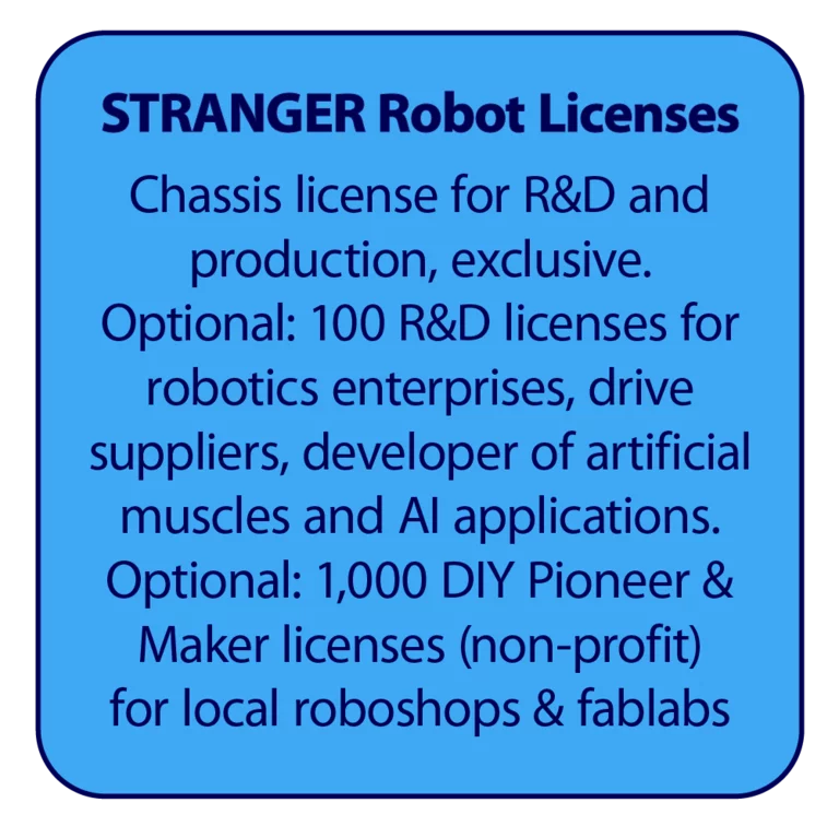
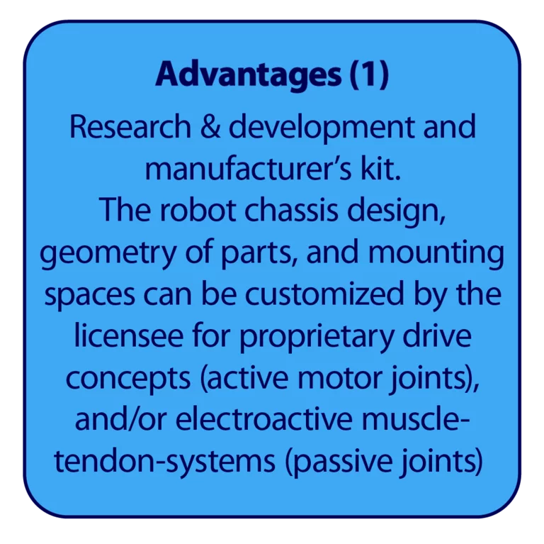
The kinematic chassis with passive joints serves as an R&D design template and, once built as a prototype, as an assembly platform into which a variety of actuators and components can be integrated, particularly artificial muscles. It is also possible to implement active motor joints using proprietary actuator technology and to adapt the chassis design accordingly.
-
The STRANGER ROBOT chassis
saves time and money in product development and testing
processes. The savings start right from the 3D CAD model:
Designing a feasible, life-size robot chassis measuring 1.8
meters typically requires several thousand hours of design
work. On top of that, there are the real-world tests of the
prototypes (the STRANGER chassis in its current form—with a
closed chassis—has already been built and sold as more than
100 times as bionic sculpture and art collector's item, and
has undergone continuous evolutionary development in the
process. The 3D model of the STRANGER ROBOT chassis,
modeled in Fusion (or other CAD-Systems)
with masses, inertias, and joints, can be adapted by the
licensee to proprietary drive concepts and internal
components and used with physics engines
such as MuJoCo (open source),
Isaac Sim (NVIDIA, free),
OPEN SIM (open source),
SCONE (open source) plus
HYFYDY (a plug-in for SCONE, but with
subscription). The conversion of XML structures to MuJoCo
is done via the URDF format, 99% of which can be handled by
AI. Isaac Sim offers native URDF/USD
support.
-
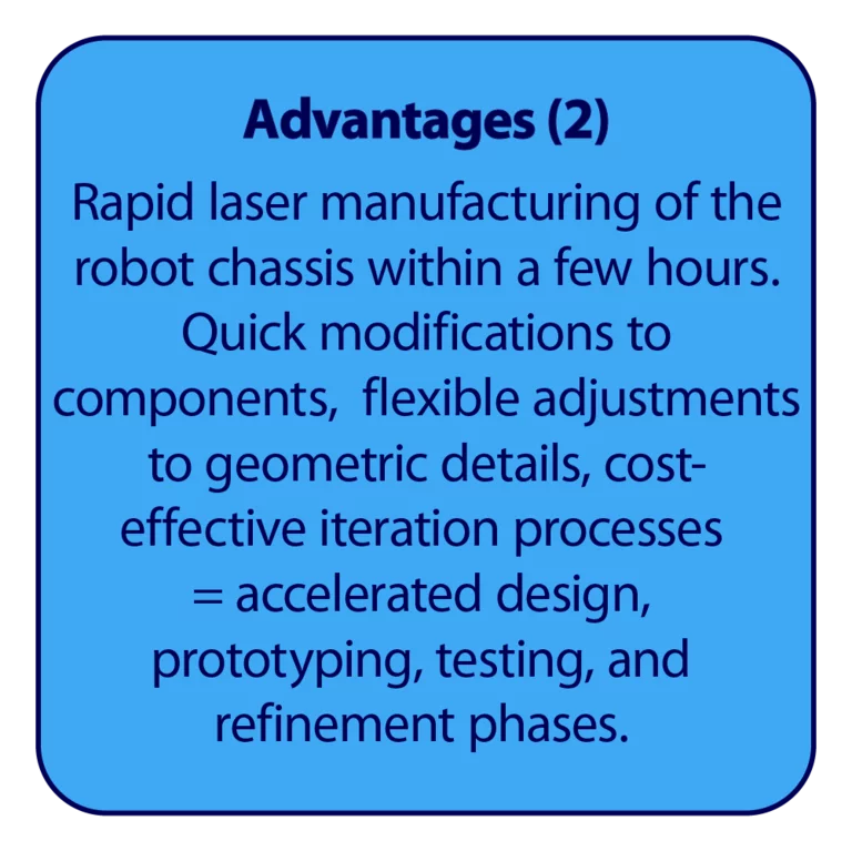
The STRANGER ROBOT chassis
can be manufactured with high precision on high-speed laser
cutting machines in just a few hours. This avoids costly
tooling and prototyping expenses from the outset and
enables rapid modifications. Rapid laser prototyping is 100
times faster & cheaper than 3D printing. Birch plywood
offers excellent lightweight material properties and
cost-effectiveness. The modulus of elasticity of the 3-ply
birch plywood used is remarkable (10,000 N/mm² along the
grain, aluminum 70,000 N/mm²), while its volume-weight is
seven times lower than that of aluminum (birch plywood 0.38
/ alu 2.7).
-
The STRANGER ROBOT chassis
forms the supporting structure. The plate-skeleton-design
provides ample installation space and protection for drives
and control modules. Frames, reinforcements, feed-through
openings, mounting points, and the assembly process are
customized to the customer’s specific components, while
maintaining the external geometry and design.
-
The STRANGER ROBOT chassis
serves as a universal R&D template and biomechanical
standard platform for humanoid robots, robot arms and
5-finger-hands. Once the custom licensee design has been
tested in the physics engine and all CAD modifications have
been completed, production of the prototype can begin. Even
after the research, development, and prototyping phases,
the plywood chassis can be quickly and flexibly adapted to
various current and future drive systems as well as to any
necessary geometric changes. Once completed and tested, the
STRANGER ROBOT chassis can serve as a cost-effective
manufacturer’s kit, particularly for on-demand production
and small-batch manufacturing.
-
The design of the STRANGER
ROBOT is timeless, not subject to fashion trends, and is
open—in the truest sense of the word—to any technology. The
type of actuators represents a variable in this design
concept. Possible options include motor joints and linear
roller actuators with elastic properties (active joints),
or muscle-tendon drives designed according to bionic
principles (passive joints), or a combination of both. The
artificial muscles could, for example, consist of
electroactive polymers, or simply of rubber strings
tensioned by electric motors.
-
The STRANGER ROBOT chassis
can be equipped with clothing and protective padding. For
mass production, the chassis could be manufactured using
light-alloy castings or other suitable materials and
technologies, e.g., laser- or waterjet-cut aluminum frames,
spot-welded. And, of course, the skeleton design can also
be covered with paintable, impact- and shatter-resistant
body parts (e.g., made of PUR-RIM, such as automotive
bumpers)
-
The STRANGER ROBOT chassis
design can be used both as a universal humanoid robot
template, biomechanical R&D platform, and as a
manufacturer’s kit. This could be of particular interest to
robotics companies and suppliers, as well as startups—and,
with AI support, even to talented makers. With the STRANGER
ROBOT design platform, you can
- accelerate the development and testing of your drive technology in the physics engine
- significantly accelerate the implementation of proprietary joint actuators and/or artificial muscles and control principles
- produce a low-cost DIY robot
- develop affordable personal robots to tap into the consumer market
- develop high-performance sports robots, and much more